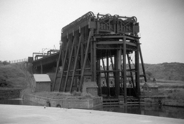
The wheels stand above the water like a second roof. In Martin Tester's July 1968 photograph of the Anderton boat lift, the framework rises from the River Weaver to banks of pulleys overhead. This is a working machine photographed midway through its long life, but its most conspicuous machinery belongs to a rebuilding. The lift opened in 1875; the great overhead assembly arrived with its conversion in 1908.[1][2]
That distinction explains the structure. Anderton's original designers put the lifting force beneath the boats. Their successors moved the load into a larger frame above them. Following that change reveals a practical problem that an elegant engineering principle could not settle: how to keep the equipment repairable while freight continued to move.
A short distance that broke the journey
At Anderton in Cheshire, the Trent and Mersey Canal passed close to the Weaver Navigation but roughly 50 feet above it. Before the lift, goods crossed that height difference through an assortment of chutes, inclined planes and warehouses. Historic England's site record describes successive additions as trade grew: the ground around the surviving structure once held a much larger apparatus for transferring cargo.[2]
The lift changed what had to be transferred. Instead of unloading goods from one vessel and putting them into another, a boat could enter a water-filled iron tank, called a caisson, and travel between the two levels with its cargo aboard. An elevated aqueduct connected the lift to the canal. Edwin Clark's design opened to traffic on 26 July 1875.[2][3]
The commercial gain lay in keeping a journey intact. Every load that stayed aboard avoided a separate handling operation at the interchange. The Canal & River Trust's historical account explicitly identifies that continuity as the lift's achievement.[4] Its spectacle—a boat apparently sailing into the air—was the visible consequence of removing work from the waterfront.
One tank helped lift the other
The first mechanism used two caissons side by side. Edward Leader Williams, the Weaver Navigation's engineer, chose a counterbalanced arrangement before appointing Clark as principal designer. Each tank rested on a hydraulic ram: a large vertical piston supported by pressurized water in a cylinder below. Supporting the tanks this way allowed a comparatively light frame around them.[5]
The two hydraulic cylinders were connected. With one tank high and the other low, a controlled imbalance could make the upper tank descend and force hydraulic water beneath the opposite piston, raising its tank. FAIRFIELDS, the contractor that later supplied the restoration's controls, describes the original operating difference as about 150 millimetres of additional water depth in the upper caisson.[6]
This was a method of making two heavy loads assist one another. The Institution of Mechanical Engineers emphasizes the resulting reduction in required power.[3] The valuable insight was to treat the descending load as part of the lifting machinery. Water served two distinct purposes: it kept a boat afloat inside its caisson, and it transmitted force between the cylinders underneath.
But balancing weight did not remove wear. The Trust's history attributes recurrent trouble in the 1880s and 1890s to corrosion associated with the salty water used in the hydraulic system.[4] A mechanism could be economical in power and still expensive in interruptions.
Put the repairs within reach
The weaknesses were more than theoretical. The National Transport Trust records a cylinder bursting in 1882, followed by failure of the other during testing. Replacement and alterations kept the lift closed for six months. Later repairs repeatedly required either closure or restricted operation.[5]
Chief engineer J. A. Saner's alternative accepted more machinery in exchange for better access. Electric motors would work through gearing and overhead pulleys; ropes would suspend the caissons, balanced by cast-iron weights. Each caisson could operate independently. The moving components would be above ground, where maintenance crews could reach them more readily.[2][5]
That bargain changed the silhouette. The structure now had to carry the suspended tanks and their counterweights. A stronger framework and foundations took over a load previously borne through the hydraulic cylinders.[5] The forest of supports in Tester's photograph is therefore evidence of a changed load path. Its bulk had a job.
The conversion also had to respect the traffic it was intended to serve. According to the Canal & River Trust, construction proceeded around the operating lift, and the new arrangement opened in 1908 after only 49 operating days had been lost.[4] This helps explain why repairability mattered so much: interruption was itself a transport cost. The mechanism had to be judged across years of use, including the days when it needed attention.
Returning to hydraulics without erasing the repair
When restoration eventually brought Anderton back to hydraulic operation in 2002, the project did not simply turn the clock back. The Heritage Fund's account describes a deliberate combination: a modern hydraulic installation, with the 1908 mechanical structure conserved in place as a static exhibit.[7]
The renewed machinery also differed beneath the surface. FAIRFIELDS explains that the restored system used pumped mineral oil and could work with both caissons together or with either operating independently.[6] The familiar idea of paired tanks survived, but the controls and working fluid reflected another generation's requirements.
This makes the preserved overhead wheels especially useful. They allow the visitor to see a solution that the functioning lift no longer needs. Removing them would have made the monument look more like its earliest version while concealing decades of adaptation. Keeping them lets the structure record the effort required to remain useful.[7]
Anderton's history can be read from bottom to top: pressure under the tanks, ropes over the wheels, then modern hydraulics within the inherited frame. The boat's task remained straightforward—stay afloat and reach the other waterway. The machinery around it kept changing because moving a load once and maintaining a dependable passage were different engineering achievements.
Sources
- Martin Tester, “Anderton Boat Lift from the SW, river level,” Geograph photograph 6075378, taken July 1968 — original photograph, date and photographer attribution.
- Historic England, National Heritage List entry 1021152, “Anderton Boat Lift, aqueduct, basins, meter building, toll houses and buried remains…” — archaeological context, cargo-transfer facilities and the 1875 and 1908 machinery.
- Institution of Mechanical Engineers, Engineering Heritage Awards, fifth edition, printed page 19 — opening date, height difference and the counterbalancing principle.
- Canal & River Trust, Anderton Boat Lift 150th Anniversary Programme (2025), printed pages 4–7 — cargo continuity, hydraulic corrosion, conversion while operating and restoration chronology.
- National Transport Trust, “Anderton Boat Lift” — design responsibilities, the 1882 cylinder failures, Saner's maintenance rationale and structural changes.
- FAIRFIELDS, “Anderton Boat Lift” project account — original hydraulic sequence and the contractor's account of the restored oil-based system and its operating modes.
- National Lottery Heritage Fund, “Anderton Boat Lift Restoration” — project objectives and the decision to conserve the 1908 mechanism alongside a modern hydraulic installation.