OpenPnP does not sell the machine its name seems to promise. It supplies the control layer that tells many different machines what a board design means in physical space. A placement exported from PCB software is only an X coordinate, a Y coordinate, an angle, a side and a component identity. Before a nozzle can act on it, somebody must establish where the board actually sits, which feeder holds the part, how high its body is, which tip can lift it, how the controller accepts motion commands and whether a camera sees the same geometry the configuration describes.
That translation is the project. OpenPnP is a GPL-licensed desktop application for surface-mount pick-and-place work, designed around a configurable machine rather than one vendor's chassis.[5] Its manual calls the software a CNC controller with camera feedback: it reads a job, plans operations and sends commands to hardware through a driver.[1] The valuable promise is therefore not “automatic electronics assembly for free.” It is narrower and more credible: make the assumptions between PCB data and a moving nozzle explicit, inspectable and reusable.
The timing is useful. OpenPnP's repository marked version 2.6 as its latest stable release on March 1, 2026, after stable 2.4 and 2.2 releases in 2025.[5] This is mature workshop software still receiving releases, not a historical build log. At the same time, its own setup material remains candid about lighting, USB topology, calibration and machine-specific configuration.[2][3] Open source gives an operator access to the control model; it does not repeal mechatronics.
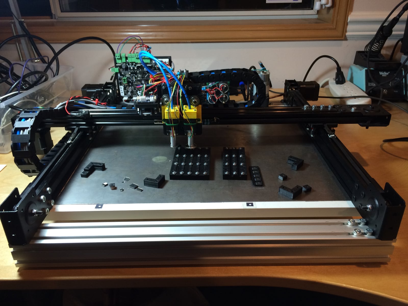
Image context: the photographed OpenBuilds machine is directly relevant because OpenPnP is not an abstract PCB editor. Its configuration has to describe a physical system like this one—axes, head, nozzles, parts presentation, actuators and controller—and keep its coordinate systems aligned during a job.[7]
The project is a control layer, not a machine design
OpenPnP's machine model is a tree. A machine can have heads; a head can carry cameras and nozzles; nozzles accept nozzle tips; feeders expose parts; actuators switch vacuum, lights or other peripherals. At the bottom of that tree, a driver translates OpenPnP's commands into the language understood by a motion or peripheral controller. The documentation names G-code, ASCII and proprietary protocols as possible targets.[1]
This boundary lets the same application sit above a scratch-built gantry, an open hardware design or a retrofitted commercial machine. It also tells adopters where portability stops. OpenPnP can decide that a nozzle should move to a location and can format the corresponding command, but the controller, wiring, limit switches, motor tuning and safety hardware determine whether that motion is physically sound. A driver is an adapter, not a certification layer.
The distinction matters because desktop manufacturing projects often blur three systems together:
- Hardware supplies stiffness, repeatable motion, vacuum, lighting and physical access to parts.
- Firmware or a motion controller executes low-level motor commands and handles I/O.
- OpenPnP holds the machine configuration, board and part data, vision procedures and job sequence.[1][2]
When a placement is wrong, that separation gives the operator a useful question: did the design data describe the wrong location, did OpenPnP map it incorrectly, or did the machine fail to reach the commanded pose? Without that boundary, every bad board becomes one undifferentiated “accuracy problem.”
It separates the board from the bench
OpenPnP's strongest data-model decision is that a board definition is not the machine configuration. A .board.xml file records placements and fiducials relative to the board's own origin. A .panel.xml file describes how boards or subpanels are arranged. A .job.xml file places one or more boards or panels on a particular run. The machine, parts and packages live in their own configuration files.[1]
That division preserves two different kinds of truth. The board file says that reference designator C17 belongs at a specific design coordinate and rotation. The machine configuration says which feeder currently supplies C17's part, which nozzle tip can pick it and how a camera relates pixels to millimetres. The first can travel with the design; the second belongs to the calibrated bench.
Placement data can be imported from CAD tools such as KiCad or Eagle, but import is not the end of setup. The operator still checks which entries are genuine placements, which are fiducials and which are deliberately not installed. Each part needs a physical height. Each board instance needs a machine-space position and a Z value for its top surface; OpenPnP adds the part height when calculating the placement height. A wrong origin can shift a whole design. A wrong part height can turn an otherwise correct X–Y move into a crushed component or a suspended one.[1]
This is why a reusable configuration is more valuable than a successful demo. A workshop that can explain its origins, rotations, heights and component identities can reproduce a job after changing an operator or rebuilding a computer. A workshop that “jogged it until it worked” has encoded production knowledge in memory and luck.
Vision closes a small, specific loop
Pick-and-place vision is not one camera performing generic intelligence. OpenPnP gives the common camera positions different jobs. A downward-looking top camera, usually mounted on the head, can locate board fiducials and parts in vision-assisted feeders. An upward-looking bottom camera observes a component after the nozzle has picked it. The bottom-vision pipeline estimates X, Y and rotational error, then passes a correction to the job processor before placement.[1][4]
Internally, bottom vision uses a configurable CvPipeline whose result is represented as a RotatedRect: a center, width, height and angle. Settings can be inherited from a global default through package and individual-part levels, which lets one common pipeline serve ordinary rectangular components while unusual packages receive specialized treatment.[4] This is a better engineering model than pretending one threshold works for every black body, silver lead, white tape pocket and reflective nozzle.
The loop is powerful precisely because its boundary is clear. Bottom vision can correct a part that sits off-center or rotated on the nozzle. It can help detect a failed pick. It does not inspect the finished solder joint, prove that the feeder contained the right component value, or compensate for a board that flexes after fiducial alignment. Those require other controls.
The build guidance makes USB topology concrete: several laptop ports can share a single USB bus, which may not provide enough bandwidth for multiple simultaneous cameras.[3] The setup guide treats camera lighting as an explicit calibration stage rather than decoration.[2] These are not side notes. If the camera feed stalls or the part edge disappears into glare, the nominal precision of the mechanics does not rescue the measurement.
Feeders are where software-defined assembly meets tape
A job cannot pick a part merely because the bill of materials names it. OpenPnP must connect that part identity to a feeder and a pickup location. Its manual distinguishes simple strip feeders, tray feeders and commanded automatic feeders. A strip feeder can begin as cut tape fixed to the bed; an automatic feeder advances material when OpenPnP triggers it. Multiple feeders can supply the same part, allowing the system to move to another source when one is exhausted.[1]
The progression sounds modular, but each step adds a physical failure mode. Cut tape can lift. A pocket pitch can be configured incorrectly. An automatic feeder can advance without presenting a part cleanly. Vacuum may fail to grip a porous or unusually shaped package. A nozzle tip that works for an 0603 resistor may be wrong for a large connector. OpenPnP exposes policies such as pausing for operator attention or deferring a failed placement, but the operator still decides whether continuing leaves a board that can be recovered.[1]
This is the practical meaning of an open manufacturing stack: failures become configurable and observable, not necessarily self-healing. The software can preserve the state of the job and offer a recovery path. It cannot know whether a skipped component makes the board harmlessly incomplete or electrically dangerous.
Maturity appears as procedure, not magic
New users can start OpenPnP in simulator mode without a connected machine, which is a good way to learn its objects and job flow before enabling motors.[1] On real hardware, the current setup guide directs users to Issues & Solutions, a system that scans configuration, keeps unresolved conditions visible and offers automatic or interactive remedies for many setup steps.[2]
The guide still names the full physical sequence beneath that assistance: driver, axes, top camera, steps per millimetre, nozzle, actuators, vacuum, bottom camera, park and discard locations, feeders, bottom vision, vacuum sensing and lighting.[2] That list is a maturity signal. The project has accumulated a vocabulary for the things builders repeatedly get wrong.
An independent retrofit provides a useful scale check, not a universal benchmark. A 2024 peer-reviewed Brno University of Technology paper documented the modernization of a full-size, four-head Tenryu MT5530LQ whose obsolete control system and MS-DOS-era programming environment had become difficult to maintain. The replacement combined OpenPnP with LinuxCNC, new control electronics and camera-based measurement. Early tests achieved roughly 2,500–2,800 components per hour, compared with about 3,000 for the original system.[6]
Those figures do not prove that another conversion will reach the same rate. They reveal the trade more usefully: the rebuilt system conceded some initial throughput while gaining compatibility with current technology, an open integration surface and a path to revive other machines with related hardware.[6] The case is also a warning against crediting host software alone. OpenPnP participated in a result produced by controls, electronics, lighting, vision, safety systems and machine restoration together. Reuse is the payoff; first-machine integration is the cost.
The right adopter owns the whole loop
OpenPnP fits a lab, hackerspace or small manufacturer that has crossed the point where hand-placing every surface-mount part is sensible, yet still needs to understand and alter its process. The team should be comfortable with motion hardware, wiring, camera calibration, component data and deliberate test runs. It should value repairable configuration and machine choice more than a single-vendor support contract.
It is a poor fit for a team expecting a downloaded application to turn an arbitrary gantry into a turnkey line. It is also the wrong place to hide requirements for guaranteed throughput, factory traceability, automatic optical inspection, safety certification or staffed service. OpenPnP can participate in commercial work—the manual explicitly frames that as within scope—but production readiness belongs to the complete machine, process and organization, not to the software license.[1]
A responsible first article is therefore intentionally boring: run the simulator; import one known board; verify origin, side and rotation; use cheap components; confirm feeder identities; test each nozzle and vacuum condition; calibrate the top and bottom cameras; exercise pause, discard and recovery behavior; then measure placement error on an unsoldered or sacrificial panel. Only after the observed board agrees with the configured board should speed optimization begin.
OpenPnP's achievement is not that it makes precision assembly effortless. It makes the effort legible. Board coordinates, machine coordinates, part identities, feeder state, camera calibration and controller commands become named interfaces instead of workshop folklore. For the team willing to own those interfaces, that software contract can be more durable than any one desktop machine.
Sources
- OpenPnP, “User Manual” — project scope, machine model, drivers, board/job/part data, feeders, configuration files, simulator and operating workflow.
- OpenPnP, “Setup and Calibration” — Issues & Solutions guidance and the ordered physical setup surface from drivers through lighting.
- OpenPnP, “Build FAQ” — computing guidance and the shared-USB-bus constraint for machine builders using multiple simultaneous cameras.
- OpenPnP, “Bottom Vision” — correction sequence,
CvPipeline,RotatedRect, inheritance and the limits of part alignment. - OpenPnP GitHub repository — GPL-3.0 project and maintenance surface, plus stable release history including OpenPnP 2.6 on March 1, 2026.
- Jan Drška, “Modernization of Tenryu Pick and Place Machine,” Proceedings II of the 30th Conference STUDENT EEICT 2024, pp. 70–73 — peer-reviewed retrofit design, integration boundaries and initial throughput comparison.
- OpenPnP,
overview_front.jpgin theopenpnp-openbuildshardware repository — direct source page and build context for the article's real OpenPnP-compatible machine photograph.