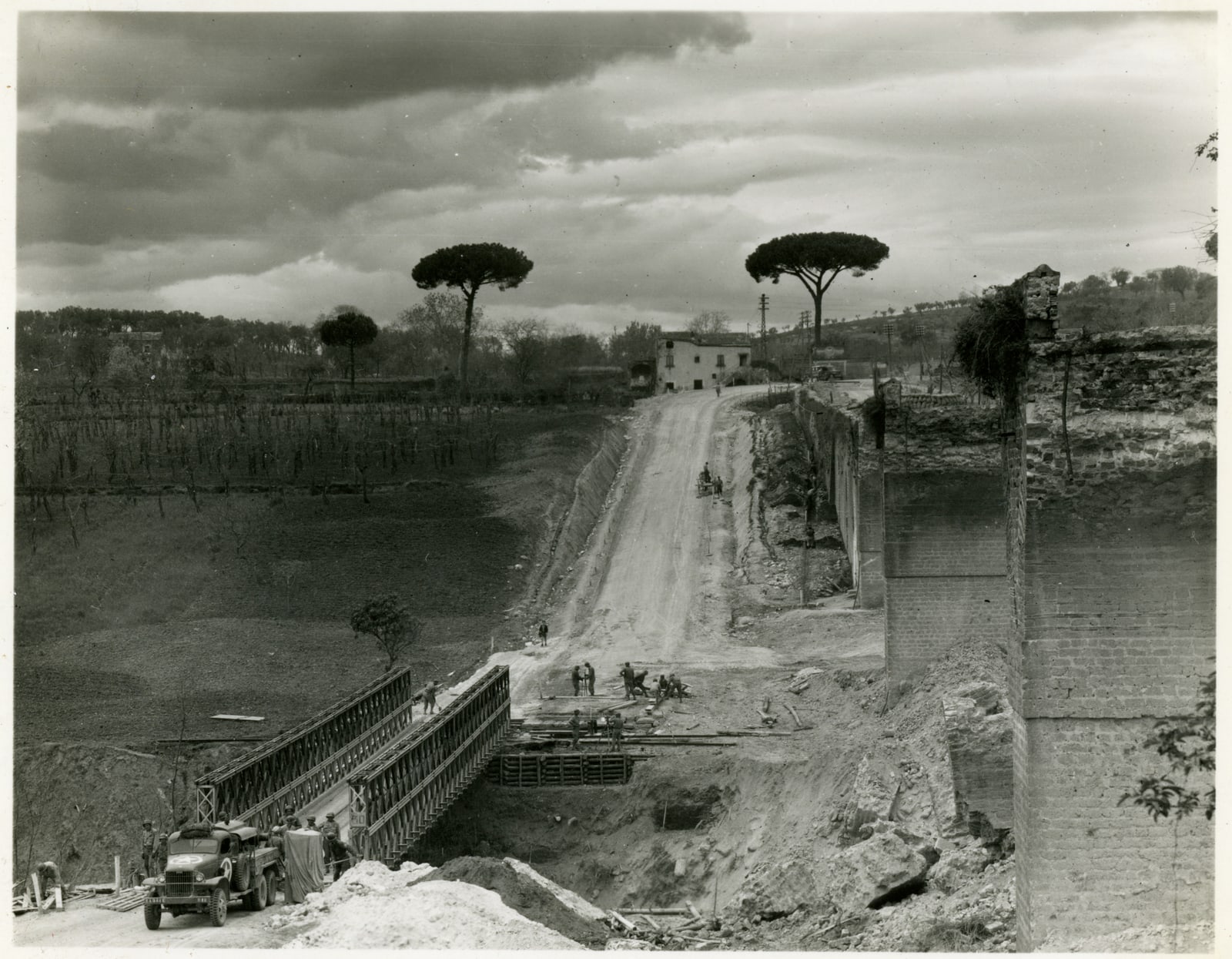
A wartime photograph preserved by the National WWII Museum catches a Bailey bridge being finished in Italy in 1944–45. The catalogue identifies the structure as portable and prefabricated: it had arrived as pieces before becoming a road. Steel trusses sit low in the foreground, beside tall remnants of masonry. Beyond them, a dirt road climbs toward houses and umbrella-shaped trees.[1]
That description leaves a practical puzzle. Small pieces are easier to transport, but how do you assemble a bridge above a space where nobody can stand? A structure strong enough to carry a tank must first survive an entirely different task: reaching the other bank under its own weight.
The Bailey system joined these problems together. Its repeatable steel panels made strength adjustable; a temporary extension helped the bridge reach across the gap. Both depended on work that a photograph of the completed crossing could easily hide.
A bridge sized for the people building it
Britain's heavier wartime tanks exposed the limits of existing bridging equipment. Donald Bailey and the Experimental Bridging Establishment at Christchurch developed a system that could be assembled quickly without a construction crane. The Mémorial Pegasus museum places production deliveries in December 1941 and the first combat deployment in Tunisia in 1942.[2]
The crucial design decision was to divide a large structure into manageable components. The U.S. War Department's 15 September 1943 manual describes the basic panel as a steel truss ten feet long and a little over five feet high, weighing 600 pounds. Six men could carry it using carrying bars. This was strenuous collective labor, but it made a crane unnecessary for lifting that component.[3]
Panels connected end to end formed the bridge's sides. Additional rows beside them, or another story above them, increased strength. Crossbeams carried the roadway between the sides. The same stock of components could therefore serve different spans and loads, with the manual specifying which arrangement belonged to which task.[3]
The point was repeatability. A longer or stronger crossing did not require an entirely new collection of custom pieces. Crews could apply familiar connections to a different arrangement. The museum's account also makes a useful distinction: field assembly used pins, bolts, and clamps, with no welding required at the crossing.[2] The prefabricated component carried some of the workshop's labor with it.
The temporary bridge in front of the bridge
For a normal launch, engineers built a light skeleton extension ahead of the roadway-bearing structure. This was the launching nose. It used bridge components but omitted the decking and the lengthwise beams that supported it. Rollers allowed the assembly to move forward from the bank.[3]
Imagine pushing a ruler off a table. At first, enough ruler remains on the tabletop to keep it from tipping. Push too far and it falls. A Bailey launch faced the same balance problem at a much greater scale. The nose reached toward the far bank while the heavier bridge behind it supplied counterbalance.
The manual required the combined structure's balance point to remain behind the near-bank launching rollers until the nose reached support across the gap. It provided arrangements for the nose and the bridge together; selecting a traffic-bearing span alone was insufficient. The unfinished crossing had its own loading conditions.[3]
Reaching the far side was another transition requiring care. The manual warned that removing the counterbalancing portion too early could overstress the nose even after the immediate danger of tipping had passed. Launching, dismantling temporary sections, and lowering the bridge onto its bearings had to follow the correct sequence.[3]
This explains why the nose mattered historically. It allowed much of the assembly work to happen on land, where men could handle components and connect them. The difficult operation over the gap became a controlled movement of an already connected structure. The temporary steel existed to make the permanent-for-now crossing possible.
The factory had to make the promise true
Standard parts offered a further advantage: material from different production runs ought to fit together. That promise was harder to deliver than the phrase “prefabricated bridge” suggests.
In his chapter for the U.S. Army Corps of Engineers' Builders and Fighters, historian Larry D. Roberts describes British production spread across more than 600 firms. Inspection gauges checked that components met common dimensions. The resulting uniformity allowed a dispersed industry to supply a single construction system.[4]
American production exposed the vulnerability. Troop tests found panels that required grinding or spreading before they would fit. A recheck in October 1943 found damaged or inaccurate gauges. Roberts reports that 850 American-made bridges acquired in 1944 had to be kept separate from British stocks because their components were not interchangeable.[4]
The significance is precise: a bridge could remain useful within a compatible set while failing the larger ambition of freely mixing Allied supplies. Repetition on a drawing did not guarantee interchangeability in a depot. The gauges used to judge the parts needed checking too.
This is the hidden counterpart to speed at the riverbank. The less fitting and alteration a crew was expected to perform under operational pressure, the more reliably that work had to be resolved beforehand. A pin that slid into place represented an industrial achievement as well as a convenient connection.
When does the construction clock start?
A National Army Museum record gives the Bailey's supply journey a particular geography. In December 1944, engineers of the 11th Division built a floating Bailey crossing of the Chindwin at Kalewa, in Burma. The museum records 28 hours of continuous assembly despite Japanese air raids.[5]
Before that timed achievement, the components had crossed the Brahmaputra by ferry, traveled by rail to Dimapur, and then covered 300 miles by lorry over mountain roads. The record belongs to an album associated with the 11th East African Division and the King's African Rifles.[5]
This floating crossing used a different support arrangement from the fixed-span launch described above. It shows how the panel system could travel into another setting, while also exposing what a construction-time headline leaves out. The 28 hours began after a considerable transport operation had brought the parts within reach.
The Bailey's success rested on making those separate kinds of work cooperate: factory inspection, loading and transport, practiced assembly, and control of an unfinished structure's weight. The tank crossing at the end was the visible result. Long before it arrived, the bridge had needed a reliable way to become a bridge.
Sources
- National WWII Museum, “A Bailey bridge is constructed by US engineers in Itlay, circa1944-1945,” accession 2007.048.087 — archival photograph and catalogue identification.
- Mémorial Pegasus, “Le Pont Bailey” — British development, crane-free assembly, production, and first combat deployment.
- U.S. War Department, TM 5-277, Fixed Steel Panel Bridge, Bailey Type, 15 September 1943, with April 1944 changes — component descriptions and sections 51–52 on the launching nose and balance; digitized manual hosted by Radionerds (PDF).
- Larry D. Roberts, “The Bailey: The Amazing, All-Purpose Bridge,” in Builders and Fighters: U.S. Army Engineers in World War II, U.S. Army Corps of Engineers, 1992, pp. 181–193, especially 186 and 190–191 — manufacturing and interchangeability; chapter scan (PDF).
- National Army Museum, “Admiral Lord Louis Mountbatten with the Royal Engineers who built the first Chindwin bridge at Kalewa, 1944 (c),” accession 1982-06-58-113 — assembly time and the preceding transport journey.